

Hydraulic hoses are made of reinforced rubber or thermoplastic and used to transport fluid in a fluid power system. They are typically reinforced with layers of braded wire to withstand the pressure in a hydraulic system.
Sizing is a primary factor when selecting a hose. If the inside diameter (I.D.) of a hydraulic hose is too small there could be pressure losses, creating excessive flow rate and generating heat which can damage the inner tube of the hose due to flow erosion. This can ultimately cause hose failure, along with clogged filters, pumps, valves and damage to seals. Additionally, if the I.D. is too large the fluid volume will exceed the work required for the equipment and make it difficult to route the hose in the allotted space. 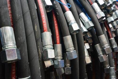
1. Hydraulic Hose Inside Diameter
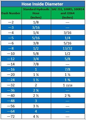
Hydraulic hose sizes are specified on the I.D. of the hose. For example, a 1/2” hose is designated as 1/2” or 0.5” in terms of decimal. For most common hydraulic hoses, the I.D. is in 1/16” increments known as the dash size. Therefore, in the example of 1/2” ID hose it is designated as –8, from the numerator of 1/2” equaling 8/16”, and a 2” hose would be 32/16 designated as –32, and so on. There are some exceptions to dash size designation such as SAE J51, 100R5, 100R14 and J2064. The table below shows designated dash sizes for standard and SAE hose I.D.
It’s important to note that the inside diameter of the hydraulic hose must be sufficient to maintain minimum pressure loss and to avoid damage that may be caused by the generation of heat or extreme turbulent flow. To determine the replacement hose ID for an existing hose assembly, read the lay line printed on the side of the original hose. If the hydraulic hose lay line is not legible on the original hose, it must be cut in order to measure the inside diameter to determine the replacement.
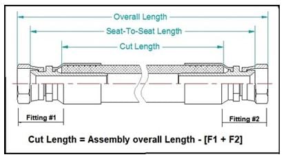
The cut length for a hose assembly is calculated by subtracting the cut-off factor (distance from the bottom of the ferrule or collar to the end of the fitting or internal sealing surface).
Source: Tribute, Inc.
2. Hydraulic Hose Outer Diameter
Hydraulic hose outer diameter (O.D.) can also be a critical factor when using hose routing clamps or routing hoses through bulkheads. The hose O.D. can vary, so it’s best to check a hydraulic fittings size chart for the proper hose O.D. to match the fitting being used.
The O.D. of hydraulic hose comprises the entire cross-section of the hose. The O.D. does not have a direct impact on the system’s pressure flow or loss calculations, though it must fit within the allotted space for the assembly.
3. Hydraulic Hose Length
The length of a hydraulic hose is the maximum distance between the two end points of the hose, measured from the end of one fitting to the end of the next. In other words, the entire hose assembly (see above diagram). Once the fittings are crimped, there may be a little stretch in the hose, but if you’re within a quarter inch you’re still good.
Be sure to consider the hose length when calculating system pressure requirements. Keep in mind: as the hose length increases, the friction losses between the fluid and the inner surface of the hose also increases, which can reduce pressure inside the system, known as pressure drop. Using a slightly larger hydraulic hose I.D. will help reduce pressure loss.
4. Hydraulic Hose Flow Rate
When sizing the hydraulic hose for proper performance, be sure to understand the flow rate of the fluid moving within the system. The flow rate in the hose is conveyed in either gallons per minute (or liters per minute) or velocity in feet per second (or meters per second). The maximum flow rate for the system is primarily determined from the pump rating. Pump rating data is usually in the pump system specifications, on the manufacturer’s tag or the manufacturer’s catalog.
Once the system maximum flow rate is established, use a nomogram to determine the appropriate selection of hose size to ensure the durability and performance for the required flow.

Additional Sources Include:
.png)