

 There are fundamental factors that need to be considered when selecting an instrumentation valve. Some of the most important criteria required for valve selection are listed below. Each application will place higher importance for each of the following factors:
- Basic Valve/Packing Designs
- Pressure Fluctuation
- Pressure and Temperature Considerations
Other key factors include flow media, codes and standards, actuator design options, and flow analysis and orifice sizing.
It is critical that all aspects of the system be assessed for proper design prior to conducting a valve specification. Understanding the variety of operating conditions will greatly affect the final design selection.
Primary Instrumentation Valve Designs
Understanding the variety of ways an instrumentation valve’s packing has been designed and the types of valve designs that are available play an important role in the specification process. At its basic core, valves consist of a control component such as a ball or a needle, and sometimes incorporate an automatic actuation device for valve operation, as opposed to manual operation. The instrumentation valve seat controls the flow of the material while the packing limits the leakage between the seat and actuation elements. The overall performance can be dramatically affected by factors such as materials of construction, rigidity, and location on the valve stem and proper valve selection. Among all of the valve designs on the market, generally speaking, the following four valve types will be used in instrumentation applications for flow control, analysis, testing and ensuring maximum safety.
Ball Valves
A ball valve consists of a ball-shaped component to stop or start fluid flow. In terms of operation, when the valve handle is turned to the open position, the ball rotates to where the hole through the ball moves in line with the valve body inlet and outlet. When the valve is shut, the ball is rotated so that the hole closes the flow opening of the valve body and the flow is stopped. Most ball valve actuators are of the quick-acting type, which only require a quarter turn of the valve handle to open and shut the valve.
The most popular instrumentation ball valves are rated for pressures up to 3,000 PSI and temperatures to 350°F (176°C) with PFA (perfluoro-alkoxy polymer) seats and are available in single (in-line), two-way angle pattern and three-way connections. High quality ball valves have pneumatically tested seats at 1,000 PSI with nitrogen at zero leakage. These ball valves should have hydrostatically tested bodies at 3,000 PSI and seats tested at 2,000 PSI.
Popular ball valve designs are available in 316 stainless steel and brass, and incorporate one-piece packing for clean and accurate samples as well as designs that allow for a drop-in fit for easy replacement of the packing.
Double Block and Bleed Valves
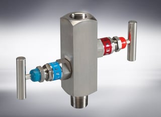 A double block and bleed valve or a DBBV takes the place of 3 separate valves, 2 isolation valves and 1 drain valve. Double block and bleed valves provide isolation from both the upstream and downstream process flow and pressure.
A double isolation and bleed valve stops process fluid from getting to an area that is being worked on. Both in-line valves are closed while the bleeder is open. If fluid were to leak past the first valve the bleeder would drain off before it pressurized the cavity between the upstream and downstream valves. If the bleeder, which may be a needle valve, were to be plugged the downstream valve would keep the process fluid from getting past it.
Needle Valves
A Needle Valve uses a precision engineered tapered pin to gradually open a space for fine control of flow. The flow can be controlled and regulated with the use of the needle. A needle valve has a relatively small orifice with a long, tapered seat, and a needle-shaped plunger on the end of a screw, which precisely fits the seat for valve shut-off.
When the needle valve screw is turned the plunger retracts allowing flow between the seat and the plunger. However, precise regulation of the flow rate can be controlled when the plunger is completely retracted. Needle valves are often used in vacuum systems where precise control of gas flow at low pressure is required. They are often used as component parts of other, more complicated valves systems.
Instrumentation needle valves are available with screwed bonnet or integral bonnet. Most are rated for pressures up to 6,000 PSI and temperatures to 450⁰F (232⁰C), and are available in straight and angle patterns.
Check Valves
A check valve (aka one-way valve) is a valve that normally allows media (liquid or gas) to flow through it in only one direction.
Check valves incorporate two-port valves, meaning they have two openings in the body, one for fluid or gas to enter and the other for the media to exit. There are various types of check valves used in a wide variety of applications. Check valves are available in many sizes, yet are typically very small. Most check valves work automatically and do not have a valve handle or stem.
Check valves close from the weight of the check mechanism when back pressure on a spring occurs, allowing the media to flow in only one direction.
Check valves have calibrated cracking pressures, which is the minimum upstream where the valve will operate. Most check valves are rated for pressures of up to 6,000 PSI and temperatures to 350⁰F (177⁰C). Depending on the application, cracking pressures are usually set at 1/3, 1, 5 10, 15, 25 and 50 PSI.
Manifold Valves
Manifolds are used in my many processing applications. They are often used to mount valves or to consolidate the plumbing configuration to interface between valves and ports that are being plumbed into. A manifold is a single block or adjoining blocks, which interface for the valves to mount to or ports for fluid transfer. The ports are then plumbed to the manifold to complete the circuit.
Because manifold valve systems can be used in modules, other valve types are easily interchangeable and easily mounted to the manifold to customize a system operated by actuators. Valves that are connected in series to manifolds can have a variety of NPT, Metric or ORB ports. This alleviates the need for developing a more complex system of various valve types with different ports, simplifying the system and saving costs.
A manifold can be used without other valves as a fluid cavity with two or more ports combined in series to reduce plumbing. For instance a return line manifold with multiple smaller ports connecting to a larger tank port can eliminate the need for a series of fittings. This lowers cost and reduces potential leak points.
Most manifolds are available in 2, 3 or 5 valve configurations:
- Two valve manifolds are used with instruments such as pressure gauges, pressure transmitters and pressure switches.
- Three valve manifolds are the most common. They can incorporate test ports on the process side and drain ports on the instrument side.
- Five valve manifolds are typically used with differential pressure instruments where drain valves are required on the instrument side. They are also common for flushing of the system and the prevention of loss of expensive fluids.
- Three and five valve combination manifolds are used with differential pressure instruments such as differential pressure transmitters, switches and pressure gauges.
Primary Design Features
Most manifold designs have case hardened swiveling stem plugs. This design is ideal for most low, medium and high pressure applications.
- High pressure gas applications typically incorporate a swiveling plug with a soft seat design. The seat materials are reinforced polytetrafluoroethylene (RPTFE), delrin and PEEK.
- High quality manifolds have a case hardened ball plug in 316 SS. Manifolds made of Hastelloy C, Monel, Inconel and titanium have tungsten carbide ball plugs.
- Manifold valves should be designed with the “thread above the seal” so that the stem threads are not wetted by the fluid flowing in the system.
- Gland sealing arrangements vary based on temperature ranges. For temperatures up to 180 °C, the material used is RPTFE. For temperatures in the 180 °C to 270 °C range, graphitized seals are used. Beyond 270 °C and up to 540 °C, Grafoil seals are used.
The choice of materials is based on the working fluid and the installation location, where atmospheric conditions may vary and require specific materials to prevent corrosion and withstand vibration.
Common manifold materials include:
- Carbon steel ASTM A105
- Stainless steel ASTM A479, A182, F304, F304L, F316, F316L and F321, and are available with conformity to NACE MR 01 75 for corrosion resistance.
When extreme corrosion resistance is required, materials are usually:
- Monel with conformity to NACE MR 01 75 for corrosion resistance
- Inconel, Hastelloy C and titanium
If you enjoyed this post and want to learn more about selecting instrumentation valves, fitting & tubing, click below to download our free whitepaper:

Sources:
- Valve Magazine
- Fluid Power World, MOBILE HYDRAULICTiPS
- Outokumpu
- Society of Petroleum Engineers
- HandyTube
- TECO Technology
.png)