

ISO connections and instrumentation fittings are two common connections found in fluid power systems. This post is an excerpt from our new Thread ID & Measurement Guide.
ISO Connections
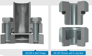 ISO/DIS 6162 4-Bolt Flange* is another common connection found in fluid powersystems. There are two pressure ratings for this connection; Code 61: PN 35/350bar which is considered the standard series Code 62: PN 415 bar which is the highpressure series.
They maintain the same design, yet with the bolt hole spacings and flanged head diameters being larger on the PN 415 bar high pressure connection. Inch or metric bolts are found in these connections, however there is an “M” stamped on the port if metric bolts are to be used. The female port of the fitting is a smooth, un-threaded port with four bolt holes set in a rectangular pattern in around the port. The male is a flanged head, with a groove for an O-ring to seat and either split or captive flange halves and bolt holes which match the port. The seal is made where the O-ring is compressed between the flanged head and the flat surface the port. The connection is held by threaded bolts.
ISO 6149 Port and Stud Ends with ISO 261 Threads and O-ring Seal though it is similar to the SAE J514 Straight Thread O-ring Boss (ORB), this type connection
incorporates metric threads. The male connector has straight threads with an O-ring. The female port is also straight threads machined surface to provide a smooth, flat, accurately located surface (minimum spotface), along with a chamfer where the O-ring seats. It seals when the O-ring is compressed into the chamfer when mating the male connection. This is also considered a mechanical connection.
Instrumentation Fittings
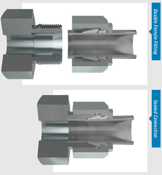 Double and Single Ferrule Instrumentation Fittings. Instrumentation fittings are widely used in fluid or gas transfer applications such as refineries, chemical plants and food processing plants. The male end of a double-ferrule instrumentation fitting has a recessed counter-bore which matches the tube O.D. being used, plus an inner cone. The seal is made between the front ferrule and the cone. The tubing is held in place by the swaging action caused by the tightening of the nut, which forces the front and back ferrules to bite into the tubing (see illustration below), firmly holding it in place. This allows for the use of un-flared tubing with these connectors.
The single-ferrule instrumentation fitting is similar, but has a larger front ferrule and no back ferrule. The sealing method is also similar. Both types of instrumentation fittings are commonly available in stainless steel and brass.
Instrumentation fittings have UNEF (extra fine) threads and sizing is determined by the outside diameter of the tubing being used.
Since you seemed interested in our instrumentation content, check our free BluePrint as a helpful resource:
