

There are many different connection types all across the world, this post will help you identify and define the common fluid connection types that are found in the US! This post is an excerpt from our new Thread ID & Measurement Guide.
.jpg?width=366&height=367&name=NPTF%20NPSM%20(1).jpg) NPT (National Pipe Thread) style pipe threads are have been widely used for over 100 years. NPT is a U.S. standard for tapered threads used on pipes and fittings. They are used to effectively seal pipes for fluid and gas transfer. The nominal pipe size can be identified by physically measuring the thread diameter, then subtracting ¼”.
NPT (National Pipe Thread) style pipe threads are have been widely used for over 100 years. NPT is a U.S. standard for tapered threads used on pipes and fittings. They are used to effectively seal pipes for fluid and gas transfer. The nominal pipe size can be identified by physically measuring the thread diameter, then subtracting ¼”.
They are available in iron or brass for low-pressure applications and carbon steel and stainless steel for high-pressure.
NPTF (National Pipe Tapered Fuel) style connections are widely used in fluid power systems. They have a tapered thread by which a seal is made by deformation of the threads. NPTF Threads are measured at the thread diameter and subtracting ¼ -inch to establish the nominal pipe size.
NPSM (National Pipe Straight Mechanical) connections are also often found in fluid power systems. The female component incorporates a straight thread with an inverted 30° seat. The male component has a straight thread and a 30° internal chamfer. A seal is made by compression of the 30° seat on the chamfer. This is considered a mechanical connection. If an NPTF male is properly chamfered it will also seal with an NPSM female connection.
Society of Automotive Engineers Thread (SAE)
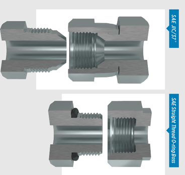 SAE J1926 Straight Thread O-ring Boss (ORB) is recommended by the National Fire Protection Association (N.F.P.A.) for leak prevention in medium and high pressure hydraulic systems. The male connection is a straight thread with an O-ring. The female port has a straight thread and a machined surface to provide a smooth, flat, surface (minimum spotface), along with a chamfer where the O-ring seats. It seals when the O-ring is compressed into the chamfer when mating the male connection. This is also considered a mechanical connection.
SAE J514 JIC/37˚ Hydraulic connections are common in most fluid power systems. Both male and female components have 37° seats. The seal is made by establishing contact between the male flared and the female coned seat. This is also considered a mechanical connection.
SAE J512 45° connections are used in automotive, refrigeration and truck pipe systems. These connectors are typically brass material. The male and female connections have 45° seats, where the seal is made where the male flare and the female cone meet. This is a mechanical connection, also.
NOTE dash sizes: -02, -03, -04, -05, -08 and -10 of SAE 37° and SAE 45° have the same threads, but NOT the same seat angles. Intermixing the two different types of fittings will result in leakage, so use care in measuring seat angles.
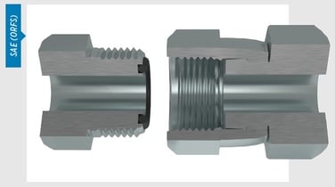 SAE J1453 (ORFS) O-ring Face Seal connections are considered the best for leak control. The male connector has a straight thread and an O-ring in the face. The female has a straight thread and a machined flat face. The seal takes place by compressing the O-ring onto the flat face of the female, similar to the split flange type fitting. The threads maintain the connection mechanically.
SAE J512 Inverted connections are typically used in automotive systems. The male connector is either a 45° flare within the tube fitting or a 42° seat in the machined adapter. The female incorporates a straight thread with a 42° inverted flare. The fittings are sealed at the flared surfaces. These threads also maintain a mechanical connection.
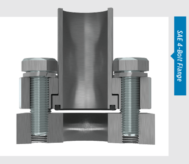 SAE J518 4-Bolt Flange* There are two pressure ratings for these connections; Code 61 which is considered the standard series and Code 62 is the 6000 PSI series. The design is the same for each series, yet the flanged head diameters and bolt hole spacing are larger for the 6000 PSI high pressure Code 62 connection. The female port of the fitting is a smooth, un-threaded port with four bolt holes set in a rectangular pattern in around the port. The male is a flanged head, with a groove for an O-ring and either split or captive flange halves and bolt holes which match the port. The seal is made where the O-ring is compressed between the flanged head and the flat surface the port. The connection is held by threaded bolts.
*Excluding bolt sizes, SAE J518, JIS B 8363, ISO/DIS 6162 and DIN 20066 are interchangeable.
Measuring Four Bolt Flanges: Use a caliper to measure the port hole, then measure the flanged head diameter or the longest bolt hole spacing from center-to-center. To correspond with Caterpillar® split flanges, CAT flanges have incorporated a 560” flange thickness. All other flange dimensions are identical to Code 62.
Since you seemed interested in our instrumentation content, check our free BluePrint as a helpful resource:
