

Selecting the correct inside diameter of fluid piping, such as steel tubing, steel pipes and hydraulic hoses
Piping should be sized to avoid drops in pressure when considering aircraft hydraulic system components. The unstable flow causes unnecessary friction between the walls of the piping and the fluid, ultimately creating lost energy in the system which will raise the temperature of the fluid. This is due to excessive fluid velocity which causes turbulence and unplanned pressure drops. By maintaining a practical fluid velocity, pump inlet conditions will be controlled which will reduce the potential of excessive heat in the aircraft hydraulic system components.
Recommendations for maximum fluid line velocities are:
• 2 to 4 feet per second for inlet or suction lines
• 10 to 15 feet per second for return lines
• 15 to 20 feet per second for pressure lines operation from 500 to 2,000 PSI
• 25 feet per second for pressures of 3,000 PSI
The following formulas should be used to ensure conductors are properly sized:
V=0.3208 *Q/A
V = velocity in feet per second
Q = Flow rate in gallons per minute
A = Area of the conductor (piping) in square inches
To find the area of the piping used:
A=0.7854*D₂ (D being inside diameter in inches)
To verify if the correct size of the pressure line converts the formula as follows:
D=√{(0.4085*Q)/V} (for example a 10 gallon per minute system that has a maximum velocity of 20 feet per second the inside diameter of the tubing should be 0.452 inches or a ½-inch diameter pipe)
The purpose of hydraulic hoses is to allow for the movement of aircraft hydraulic system components on heavy equipment and industrial power units. Hoses are used where rigid lines will crack or break under these conditions. They are found on a pump’s suction lines, discharge and case drain. You can use the hose’s layline as a visual index when routing and tightening the assembly to ensure the hose is not twisted or kinked. Use the layline to determine the right hose, its required size and ensure it is plumbed correctly. Hydraulic hoses should be visually marked in accordance with SAE J517. Though all piping on new equipment, including hoses, is unlikely to be shipped with any deformity, it’s important to give a visual inspection prior to putting it into service. Even a 7-degree twist can cause up to 90 percent loss of the hoses’ service life.
Selection of Fittings and Connectors
The proper selection of connectors or fittings is imperative and must be leak-free. Hydraulic systems commonly incorporate one or all of three styles of fittings:
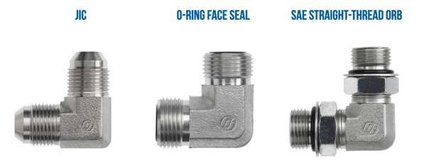
Fittings seal the hydraulic fluid within the system with either all-metal fittings that have metal-to-metal connections, or O-ring fittings which contain the pressurized fluid with compressed elastomeric seals. In both cases, it is imperative that the fittings be tightened to system specifications to form a high-pressure seal. Over tightening will cause cracks, leaks or even a rupture which can lead to a dangerous system failure.
This blog is an excerpt from our whitepaper, Hydraulic Safety Begins With the Design. Click here or the link below to download your free whitepaper!

Primary Sources Include
- Grading & Excavation Contractor
- Hydraulics & Pneumatics 1
- Hydraulics & Pneumatics 2
- Machinery Lubrication
- Society of Tribologists and Lubrication Engineers
- Swedish Institute of Standards
.